

Panel builders designing low-voltage and medium-voltage switchgear face a recurring engineering challenge: how to size and specify busbar supports that will survive the electrodynamic forces generated during a short-circuit fault. Understanding the mechanics behind these forces — and selecting insulation hardware engineered to withstand them — is central to safe, compliant switchgear design.
Understanding Short-Circuit Forces in Busbar Systems
When a short-circuit occurs in a power distribution system, the fault current flowing through parallel busbars generates electrodynamic repelling forces between the conductors. This is a well-documented physical phenomenon in power distribution engineering: the higher the fault current and the closer the conductor spacing, the greater the mechanical force exerted on the busbars and, by extension, on the supports that hold them in place. Busbar supports are therefore not passive components — they are structural elements that must resist these forces without cracking, deforming, or allowing conductor movement that could lead to phase-to-phase flashover.
Why Busbar Supports Matter During Fault Conditions
According to DOWE's industry pain point insight, short-circuit electrodynamic forces place direct mechanical stress on busbar supports, while thermal cycling simultaneously causes differential expansion between copper or aluminum busbars and the composite supports holding them. A support that is only rated for continuous current but not for short-circuit withstand can fail at the exact moment protection is most needed. This is why busbar support specification requires looking beyond rated current alone and evaluating short-circuit withstand current (Icw), mechanical pull-out resistance, and thermal compatibility as a combined system.
Key Factors That Determine Short-Circuit Force Magnitude
Panel builders evaluating busbar support requirements should account for several interrelated factors:
- Rated current and system voltage — Busbar support systems must be matched to the voltage class and current rating of the installation, from standard low-voltage switchgear up to 1,100V AC and 6,300A.
- Short-circuit withstand current (Icw) — Supports in utility substations and high-current industrial installations must handle peak fault conditions; DOWE's HC Heavy Duty series is engineered for Icw up to 100kA/1s.
- Phase configuration and bar count — Installations vary between 3-pole, 4-pole, single-phase, and multi-bar-per-phase arrangements, each of which changes the mechanical loading pattern.
- Mounting and clamping geometry — Pre-molded or modular interlocking designs reduce installation variability and maintain consistent phase-to-phase spacing under fault conditions.
Material and Mechanical Requirements for Busbar Supports
Because electrodynamic forces act directly on the composite body of a busbar support, material selection is a core engineering decision. DOWE constructs its busbar support and clamping systems from high-strength SMC (sheet molding compound) using longer glass fibers of 25mm to 50mm, which delivers superior flexural and tensile performance compared to standard compounds. Independent of fault events, the mounting inserts themselves must resist pull-out: DOWE's threaded insert systems demonstrate tensile pull-out resistance greater than 8,000 N for M8/M10 inserts, with torsional lock exceeding 1.5 times the bolt proof torque — both of which are directly relevant to a support's ability to stay seated during a sudden electromagnetic shock.
Matching Thermal Expansion to Prevent Long-Term Stress
Short-circuit events are not the only source of mechanical stress on busbar supports. Repeated thermal cycling under normal load also causes expansion and contraction differences between metallic busbars and composite supports. DOWE addresses this by engineering its composite formulations to a coefficient of thermal expansion (CTE) of 15–22 × 10⁻⁶/K, which is aligned with copper (16.5 × 10⁻⁶/K) and aluminum (23.1 × 10⁻⁶/K). This alignment reduces the cumulative mechanical fatigue that can weaken a support well before a fault event ever occurs, meaning a support that passes short-circuit testing in isolation must also be evaluated for long-term thermal compatibility.
DOWE Busbar Support & Clamping Systems: Engineered for Fault Conditions
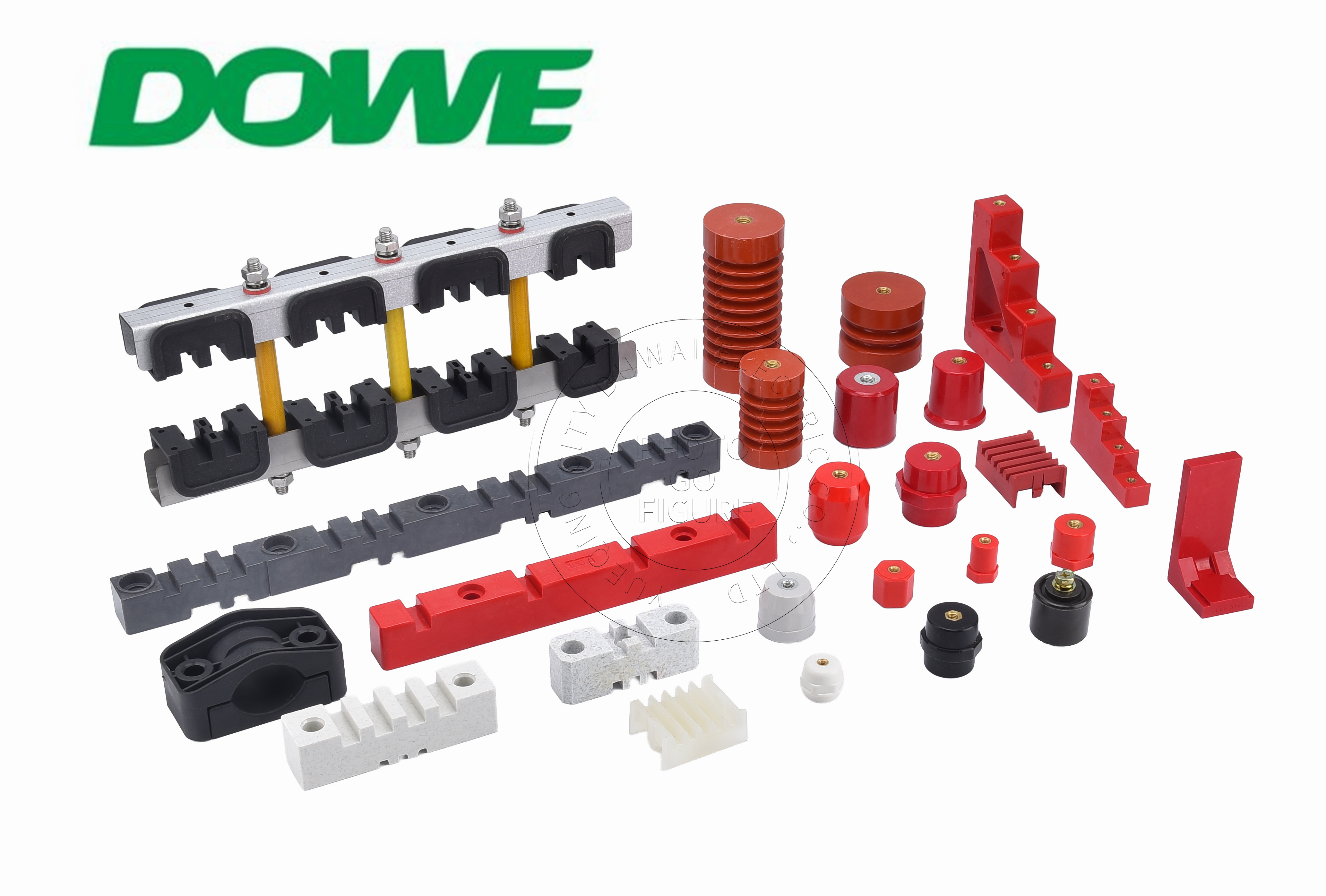
Yueqing City Duwai Electric Co., Ltd., operating under the DOWE Electric brand, offers a structured range of busbar support and clamping systems rated up to 1,100V AC and 6,300A, purpose-built to retain multiple parallel phase conductors in fixed spacing against electrodynamic repelling forces.
The EL Series is a universal pre-molded busbar support for 3-pole and 4-pole configurations rated from 250A to 2,500A, built from high-strength SMC. Its pre-molded spacing options — EL-130, EL-170, and EL-210 — eliminate manual spacing verification and provide repeatable phase-to-phase distances, which is particularly relevant since these dimensions reference ABB MNS, Schneider Blokset, and Siemens Sivacon mounting hole centers, busbar slot spacing, and creepage dimensions without requiring panel redesign.
For the most demanding fault conditions, the HC Heavy Duty series offers single and multi-pole modular busbar supports rated up to 6,300A with short-circuit withstand of Icw up to 100kA/1s, constructed from high-strength BMC/SMC. This series is specifically positioned for utility substations and high-current industrial installations where extreme fault currents are a design consideration.
The XD3-D4 Series addresses installations with variable busbar bar counts, offering 3-phase and 4-phase combination supports in a modular interlocking design that accommodates 1 to 3 bars per phase across a rated current range of 630A to 1,600A, using SMC thermoset material.
For lighter-duty branch circuit applications, the Single / Three Phase clamp series provides modular busbar clamps rated 100A to 1,250A in BMC/DMC material, delivering dependable insulation for phase splitting and branch take-off configurations at a cost-effective price point.
Verification and Compliance for Panel Builders
Panel builders ultimately need documented proof that busbar support systems meet applicable standards before completing switchgear assemblies. DOWE's components are produced in compliance with IEC 61439-1/2, IEC 60664-1, IEC 60273, IEC 60071, and IEC 60815, and carry UL 94-V0 flammability certification, RoHS and REACH compliance, CE clearance, and SGS third-party type test clearance. These SGS reports allow panel builders to reference third-party type testing to complete Design Verification documentation without independent destructive testing, which directly supports compliance workflows under IEC 61439 assembly verification requirements.
Practical Guidance for Specifying Busbar Supports
For panel builders and EPC contractors evaluating busbar support requirements, the practical sequence is to first confirm the system's rated current and short-circuit withstand requirement, then select a support family matched to that current class — EL Series for standard 250A–2,500A assemblies, HC Heavy Duty for installations requiring Icw up to 100kA/1s, XD3-D4 for variable bar-count configurations, or Single/Three Phase clamps for branch circuits — and finally confirm that the dimensional footprint matches the target enclosure platform. DOWE's 1:1 drop-in OEM replacement capability for ABB MNS, Schneider Blokset/Okken, Siemens Sivacon, GE, and Eaton switchgear platforms means this specification process can often be completed without redesigning existing panel architecture, reducing engineering time while maintaining documented compliance with international dielectric and mechanical standards.
http://www.busbarinsulator.com
Yueqing City DUWAI Electric Co.,LTD